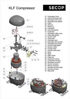
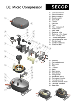
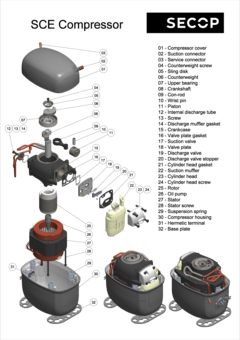
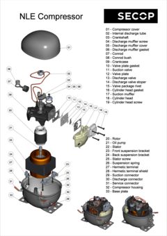
The Compressor, Its Components, and Their Function
Type label
The type label that can be found on every hermetic compressor contains critical information for the customer or user, as well as for the dispatch process. Details include the type of compressor, the refrigerant which it is designed for, the frequency, and the mains voltage.
Connectors
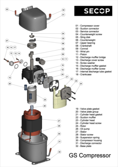
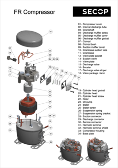
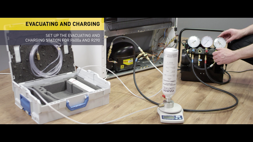
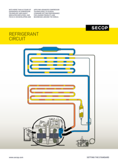
The suction connector is used to suck the refrigerant into the compressor with the process and discharge connectors located on opposite sides. Compressed refrigerant is discharged from the compressor via the discharge connector. The process connector allows the cooling system to be charged with refrigerant after the compressor has been installed. This process would usually take place in a final stage at the manufacturer’s assembly line.
Electrical connection
The electrical connection can be seen on the outside of the compressor. Depending upon the type of device being purchased, starting equipment is sometimes preassembled together with an appropriate protective plastic cover.
Compressor housing
The compressor shell is constructed from a steel sheet with the top cover welded together with the bottom housing. That connection is hermetically sealed, ensuring that refrigerant cannot leak to the outside. In order to guarantee that the mechanical unit (motor, cylinder, and valve) of the hermetic compressor remains within the center of its housing, four springs are used to keep it in its dedicated position. The external interfaces of the shell include two baseplates that enable the compressor to be mounted within the appliance.
Motor and stator
The motor is of key importance to the compressor and consists of a stator, rotor, and power cable. It is a priority to ensure that noise levels are kept to a minimum, and the motor is mounted on springs for this reason which results in reduced levels of vibration.
The stator consists of a stator stack, together with two windings of copper wires. The stator stack is constructed using sheet metal. The windings are suitably protected to ensure that damage from loose wires can be avoided. By contrast, the rotor has an iron core, cast in aluminum.
Electrical start equipment
The provided electrical starting device must be suitable for the individual compressor. The starting device is responsible for starting the hermetic compressor and does so by supplying the necessary power to enable the start winding to be activated. Once the compressor has started to rotate, power is supplied via the motor to the main winding. A flexible connection to the motor is provided via the power cable.
Pump unit
The piston and cylinder unit contains four distinct elements: a block, discharge tube, crankshaft, and piston. The discharge tube is mounted upon the block, with an oil pump mounted at the bottom of the crankshaft. The piston has a piston rod which is connected via a piston pin. Two discharge chambers are contained within the block and are used to enable compressed refrigerant to make its way to the discharge connector.
The flexibility of the tube itself is increased by turns of the discharge tube. The crankshaft is securely connected to the rotor, transforming the rotations of the motor into strokes of the piston. As a result of these piston strokes, the cylinder moves up and down. It's this movement that allows refrigerant to be sucked in, then compressed, and finally discharged.
The valve unit makes use of a discharge valve and suction unit, which are both installed on the main valve plate. The valves assist with opening and closing the valve plates during the suction and discharge processes.
This action allows the hermetically compressed refrigerant to make its way into the discharge chambers. Finally, a muffler is used to reduce the noise that is created by the suction process. It is fitted between the suction connector and the suction side of the pump unit.


